


Serial interfaces

NOTICE
Damage to the serial communication interface by using 5-pin terminal block of the TA5101-4DI!
If the 5-pin terminal block of the TA5101-4DI option board is plugged into a option board for COMx serial communication TA5141-RS232I, TA5142-RS485I or TA5142-RS485, the communication interface will be damaged by the 24 V.
Please do not confuse the 5-pin terminal block of the TA5101-4DI with the 5-pin terminal block for serial communication interface of TA5141-RS232I, TA5142-RS485I or TA5142-RS485.
|
Serial interface |
Pin |
Signal |
|---|---|---|
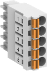 |
1 |
A1 internally connected to A2 |
|
2 |
B1 internally connected to B2 |
|
|
3 |
GND |
|
|
4 |
A2 internally connected to A1 |
|
|
5 |
B2 internally connected to B1 |
Protocols
|
No. |
Protocol |
Description |
|---|---|---|
|
1 |
Modbus |
Modbus RTU, master or slave |
|
2 |
CAA SerialCom |
Support for blocks contained in the CAA_SerialCom.lib library |
Bus cable
|
Bus line |
|
|---|---|
|
Construction |
2 cores, twisted, with common shield |
|
Conductor cross section |
> 0.22 mm² (24 AWG) |
|
Twisting rate |
> 10 per meter (symmetrically twisted) |
|
Core insulation |
Polyethylene (PE) |
|
Resistance per core |
< 100 Ω/km |
|
Characteristic impedance |
ca. 120 Ω (100 Ω ... 150 Ω) |
|
Capacitance between the cores |
< 55 nF/km (if higher, the max. bus length must be reduced) |
|
Terminating resistors |
120 Ω ¼ W at both line ends |
|
Remarks |
Commonly used telephone cables with PE insulation and a core diameter of > 0.8 mm are usually sufficient. |
|
Cables with PVC core insulation and core diameter of 0.8 mm can be used up to a length of approx. 250 m. In this case, the bus terminating resistor is approx. 100 Ω. |
|
Cable length
The maximum possible cable length of a serial connection subnet within a segment depends on the transmission rate.
RS-485 for point-to-point or bus connection:
|
Parameter |
Value |
|---|---|
|
Transmission rate |
9.6 kbit/s to 115.2 kbit/s |
|
Maximum cable length |
On request |
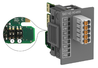
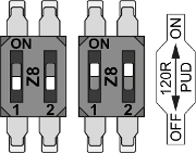
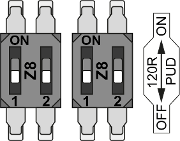
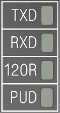
Bus termination
The line ends of the bus segment must be equipped with bus terminating resistors. These resistors are integrated in the module TA5142-RS485I. The pull-up and pull-down settings must also be made on the circuit board of the module.
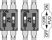
- 1
-
Termination resistance settings
- 2
-
Pull-up and pull-down settings
|
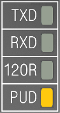
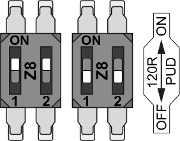
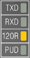
Settings on the module |
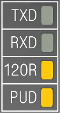
State of LEDs |
Internal wiring diagram |
Description |
|---|---|---|---|
 |
 |
 |
Master at the bus line end, pull-up and pull-down activated, bus termination 120 Ω |
 |
 |
 |
Master within the bus line, pull-up and pull-down activated |
 |
 |
 |
Slave at the bus line end, bus termination 120 Ω |
 |
 |
 |
Slave within the bus line |