All settings related to the application and axis specific will be done here and need to be carefully updated for each axis. Based on the inputs provided here, wizard will compile and generate the code.
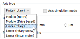
“Axis type”
The user can select the type of axis to be configured based on the application requirement.

Below is the list of settings which user can configure from the “Motion Control Wizard” along with their meanings:
|
Axis type |
Detail |
Max Limit (Counts) |
|---|---|---|
|
Modulo (rotary) |
By selecting the “Modulo” (rotary) your axis will be configured as a roll-over axis and the desired modulo range can be configured later. |
2^31-1 |
|
Modula (Drive based) |
Tis option to be selected when you have a drive which can be configured in Modulo inside the drive. |
2^31-1 |
|
Finite (rotary) |
Default setting in the wizard. Your axis will be configured as a roll-over axis where in modulo range is non editable by the user and calculated based on the “Unit” selection, Inc_Per_R, U_Per_Rev_Nominator and U_Per_Rev_Denominator setting. |
2^30 (unidirecton) 2^39 (Bidirection) |
|
Linear (rotary screw) |
This needs to be configured when the user having a rotary motor with linear movements (linear axis). |
2^31-1 |
|
Linear (linear motor) |
This needs to be configured when the user axis is a linear motor. |
2^31-1 |
|
Axis simulation mode |
This option is read only from here and needed when the user configured the axis but not have the real hardware yet. This can be selected from the “Motion Solution Wizard” overview page. Virtual axis configuration. |
NA |
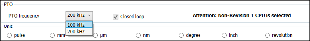
“PTO ” (Hardware settings)
With “Revision 1 CPU” or higher, by default 4 * 200 kHz PTO axis is supported, there is no special settings needed in the axis configuration page.

If a “Revision 0 CPU” is used, user can set the PTO axis frequency to 100 kHz or 200 kHz using the drop down as shown below. Based on the PTO axis frequency selection, the onboard I/O configuration will be updated.
“Closed loop”
By default, the PTO axis is open loop and however user can also configure a maximum of two PTO axis as closed loop.
To configure the axis as closed loop, user need to configure an encoder axis -> encoder source -> encoder channel -> encoder purpose as the PTO axis which needs to be a closed loop axis.
“Unit”
Based on the application requirement user can select the desired unit in the wizard and the wizard will update the subsequent parameters to the selected user unit.
From the below picture user can find the currently supported unit formats.

As an example, when the user selects the axis type as “Modulo (rotary)” and unit as degree, the wizard will update the subsequent parameters to the selected user unit and fill with default values, ex: modulo range = 360 degree (default). However make sure the user updates the subsequent parameters as per the actual application requirement.
For rotary axis the units mm, µm, nm, and inch might lead to inaccuracy due to rounding errors.
“Pulses per revolution scaling”
When the axis is open loop, user can update the “Pulses per revolution scaling” with the steps per revolution.

When the PTO axis is open loop, it is important that the user set the steps per revolution and maximum rpm by keeping the PTO frequency limits into consideration.
For example, for a 100 kHz PTO axis if the steps per revolution is 2000, the maximum rpm the axis can support is 3000 rpm (= 2000 * 3000/60 = 100 kHz)
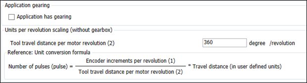
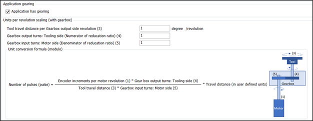
“Application gearing”
Based on the actual application requirement, here user can check/uncheck the “Application has gearing” check box. Here the user can also update the required tool travel distance per motor revolution.
When the user unchecks the “Application has gearing”, user can update the “Tool travel distance per motor revolution” as per the application requirement as shown in the below picture.
When the user checks the “Application has gearing”, user will be prompted to provide the gear box details additionally as shown in the below figure and during the generate application, the wizard will update the same accordingly.
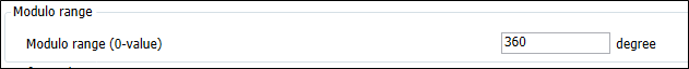
“Modulo range”
The user can provide the “Modulo range” here. This is the value at which the axis position will wrap back to zero. This window will be active only when the user selects the axis type as any of the rotary axis.
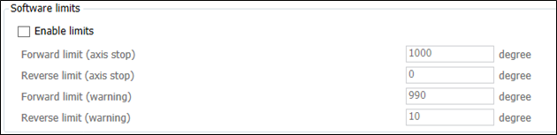
“Software limits”
The user can configure some of the common “Software limits” from the wizard itself. Below is the list of software limits which user can configure from the wizard in the selected application units.
By default, software limits in wizard are not enabled and user need to enable the same by enabling the check box “Enable limits”.
“Direction correction”
In some of the application we need to change the relationship between its real direction and that within the PLC program. By default, the check box will be unchecked, and the direction will be normal. By selecting the check box “Invert direction” both actual and reference position will be inverted, and the axis will move in opposite direction.

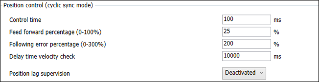
“Position control (cyclic sync mode)”
Here the user can configure the parameters related to position control and supervision. Details of each parameter is explained in our system technology chapter.
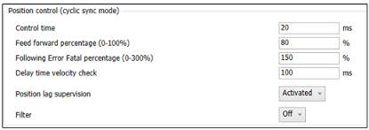
Filter off - No filtering is applied.
Velocity filter – several samples are used to smooth out the velocity calculated in the kernel.
Position filter – A linear regression calculation is used to smooth out the position values read by the kernel.
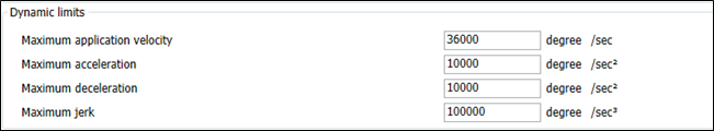
“Dynamic limits”
Users can update the maximum limits here. Some parameters depend on the drive settings and needs to be set correctly to get the desired result.
The user can set the “Maximum application velocity” to a desired value to limit the maximum application speed.
“Drive based limits”
Maximum reference value is the maximum frequency of the drive in which it reaches the maximum rpm. In some drives, the calculated maximum reference value may need to be modified, and user can select “Modify” box and change the value. Note, we have the hardware limitation as 100 kHz or 200 kHz based on the configuration and user must make sure this limitation is not crossed.
Maximum speed is recommended to keep the same maximum speed at the drive and at the PLC parameter.

Currently the applications torque limits in the wizard are not valid for PTO axis and this is ignored.
When the PTO axis is open loop, it is important that the user set the steps per revolution and maximum rpm by keeping the PTO frequency limits into consideration.
For example, for a 100 kHz PTO axis if the steps per revolution is 2000, the maximum rpm the axis can support is 3000 rpm (= 2000 * 3000/60 = 100 kHz)
When in closed loop, set the maximum rpm for the axis to reach when the maximum PTO axis frequency is provided.
For example, if the axis is configured as 200 kHz and closed loop, set the maximum rpm for the axis to reach when the 200 kHz frequency is achieved.
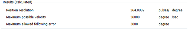
“Results (calculated)”
Based on the inputs provided, wizard will calculate the results and can be viewed immediately at the end of the configuration page.